

Top Through Hole Resistor Types and How to Choose the Right One
2026-07-18
Through hole resistors might seem old-school, but they're still the backbone of countless circuits. With so many types out there, picking the right one can feel like hunting for a needle in a haystack. From carbon film to wirewound, each has its quirks and sweet spots. And when precision really matters, you need a partner you can trust—like Milliohm, where quality isn't just a buzzword. Let's cut through the noise and get you up to speed on choosing the perfect resistor for your next project.
A Survey of Common Through-Hole Resistor Formats
Through-hole resistors remain a staple in prototyping and repairs, yet their physical formats often confuse newcomers. The most familiar type is the axial-lead resistor, with wires emerging from both ends, designed to span across printed circuit board holes. These are typically color-banded to denote resistance, and their cylindrical bodies come in standard sizes like 1/4W or 1/2W, with the larger ones handling more heat. A less obvious but equally common variant is the radial-lead resistor, where both leads protrude from one side, allowing vertical mounting that saves board space. Spotting these in older audio gear or power supplies is almost a rite of passage for tinkerers.
Beyond these two, specialized through-hole formats cater to niche demands. Fusible resistors, for instance, double as safety devices by intentionally burning out under excessive current—a clever trick that prevents circuit damage. Precision wire-wound types, often housed in ceramic or silicone, prioritize stability over compactness and thrive in high-temperature environments. Another curiosity is the zero-ohm resistor, which looks identical to a regular one but serves as a configurable jumper on automated assembly lines. Each format reflects a deliberate engineering choice rather than mere convention, reminding us that even the humblest component has a story.
In practice, choosing a through-hole resistor involves more than matching ohms; the mechanical package dictates airflow, lead bending, and durability under vibration. While surface-mount parts dominate modern electronics, these older packages still surface in high-power applications, educational kits, and restoration projects. Their enduring presence speaks to a simple truth: sometimes, a component you can see and solder by hand remains the most practical solution, long after industrial trends have moved on.
Material Choices That Define Electrical Characteristics
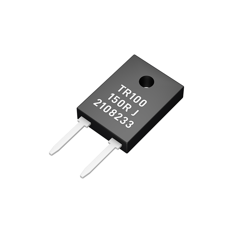
Every conductor, insulator, and semiconductor inside a component leaves its fingerprint on the electrical behavior. Start with copper versus aluminum traces—copper’s lower resistivity directly shrinks I²R losses, but switching to aluminum for weight savings forces wider traces and can shift parasitic inductance. Dielectric selection is equally decisive; FR-4 works for routine digital boards, yet a high-speed design might demand low-loss laminates like Rogers materials to preserve signal edges. Even the plating finish matters: ENIG provides a flat surface for fine-pitch parts, while HASL can introduce subtle impedance bumps that degrade eye diagrams at multi-gigabit rates.
Resistive elements tell a similar story. Thin-film resistors on ceramic substrates give you tight tolerances for precision analog, but thick-film types absorb moisture and drift over time. In high-voltage dividers, the bulk resistivity of the ceramic substrate itself can become a parallel leakage path, corrupting measurement accuracy unless guarded rings are etched into the layout. Capacitor dielectrics are notorious for introducing non-linearity—X7R ceramic loses capacitance under DC bias, which can detune a filter when signal swings grow; NP0/C0G remains stable but occupies more board space. Electrolytics bring ESR that rises as they age, quietly altering switching-regulator loop stability.
Magnetics and connectors are often the last piece of the puzzle where material choice sneaks in. A ferrite core’s permeability curve limits energy storage before saturation, forcing a trade-off between inductance and peak current. In connectors, brass contacts cost less but develop micro-fretting corrosion under vibration, raising contact resistance intermittently; beryllium copper contacts maintain spring force and resist that degradation for far longer. The common thread? Materials are never neutral—they actively shape noise margins, thermal drift, and long-term reliability in ways that schematic symbols never reveal.
When Through-Hole Components Shine in Modern Designs
In an era where surface-mount technology dominates, through-hole components retain a quiet but critical presence. Their durability under mechanical stress makes them indispensable for connectors, switches, and large capacitors that need to withstand repeated force. Designers often turn to them when a board must endure vibration or physical wear, because a pin soldered through a hole simply won't lift like a tiny SMD pad.
There's also an overlooked advantage in prototyping and repair. Through-hole parts are easier to hand-solder and replace without specialized equipment, which matters in low-volume or field-serviceable products. A technician can quickly swap a burnt resistor or a faulty transistor without destroying the board—something far trickier with miniature SMDs. This practicality keeps them alive in industrial controls, instrument clusters, and hobbyist projects where accessibility is key.
Surprisingly, through-hole components even find their way into precision analog circuits. The lead inductance that many designers try to avoid can be deliberately used to shape frequency response in RF or audio filters. Plus, the strong mechanical bond reduces microphonic effects in sensitive paths, making through-hole resistors a subtle choice for high-gain amplifiers where every vibration counts. It's a quiet niche where old-school construction outperforms modern assumptions.
Reading Resistor Labels Like a Seasoned Engineer
Seasoned engineers rarely squint at color bands or fumble with multimeters for basic resistor identification. They’ve internalized the color code so deeply that a glance at a 4-band resistor immediately registers as “47k with 5% tolerance” without mentally reciting “yellow-violet-orange-gold.” This fluency comes from years of handling parts, where the brain wires itself to recognize patterns rather than decode symbols sequentially. They might even spot a 1% 100Ω resistor from across the workbench simply by the combination of brown-black-black-black-brown, which would stump someone still counting on their fingers.
Another trick up their sleeve is reading the physical size and body material as part of the label. Through-hole resistors follow standardized form factors; a 1/4W carbon film part looks different from a 1W metal oxide one, and seasoned eyes use that context to instantly bracket the expected value range. They also know that certain values, like 220Ω or 10k, pop up so frequently that they start treating those color patterns as visual words rather than separate digits. This contextual reading eliminates the hesitation newer hobbyists experience when faced with faded stripes or oddball color sequences.
Surface-mount devices demand a whole different mindset: three-digit codes (like 103 for 10k) become second nature, and EIA-96 markings for precision parts are decoded without reaching for a lookup table. Veterans also know the pitfalls—reading a resistor upside down on a dense PCB can turn 10k into 1M if you’re not careful, so they orient themselves against the board’s silkscreen or nearby reference designators. Over time, this blend of direct pattern recognition, physical intuition, and manufacturing shortcuts makes reading resistor labels feel less like a task and more like a natural language spoken by the hardware itself.
Balancing Power, Tolerance, and Temperature Ratings
Every component lives on a thermal knife-edge. Push the power handling too high and you risk drift, noise, or outright failure—yet over-specify the tolerance and the circuit becomes a costly, bloated design. The sweet spot is rarely a single number. A 1% resistor might hold steady at room temperature, but climb to 85°C and that same part can wander outside its band before you notice the shift on the rails. Understanding how the temperature coefficient interacts with actual power dissipation—derating curves, hotspot proximity, board copper weight—turns guesswork into a deliberate choice.
Tolerance isn’t a fixed promise; it’s a warranty with fine print. High-precision parts often assume a narrow operating window, and once you step out—say, sustained high humidity or pulse loading—the initial accuracy erodes. Designers who rely solely on the datasheet limit line miss what happens when a 1206 resistor handles 70% of its rated wattage on a cramped inner layer. The actual temperature can spike well above ambient, causing a temporary tolerance blowout that eludes standard simulation models. Mapping these real-world gradients, whether through thermal imaging or careful bench testing, builds a dependable picture of where the design can safely roam.
The interplay gets trickier when you stack multiple ratings: a MOSFET’s RDS(on) might look generous at 25°C but doubles by the time the junction reaches its limit, all while your gate driver’s propagation delay shifts subtly with temperature. Rather than chasing a single “best” component, it often makes sense to treat the trio—power, tolerance, and temperature rating—as a system that can be nudged. Slight improvements in airflow, a thicker copper pour, or relaxing a tolerance from 0.5% to 1% can widen the safe operating area dramatically, giving you a design that doesn’t just calculate correctly on a spreadsheet but survives the messy reality of an enclosure.
The Subtle Art of Matching Resistors to Real Circuits
Matching resistors in a real circuit goes far beyond simply reading the color bands. A 1kΩ resistor on paper rarely behaves like a pure 1kΩ in practice—temperature, voltage, and even the PCB layout all leave their fingerprints. The true art lies in anticipating these parasitic effects before they sabotage your design, turning a simple component choice into a delicate balancing act.
Take gain-setting networks in precision amplifiers, for example. A 0.1% tolerance mismatch might seem acceptable, but when you factor in the thermal drift of each resistor across a 50°C swing, the ratio can drift enough to ruin your common-mode rejection. Subtle choices—like using matched networks on a single substrate or placing critical pairs physically close on the board—often matter more than the absolute precision of individual parts.
Then there’s the hidden world of excess noise and stray capacitance. A metal film resistor might measure perfectly on a DC ohmmeter, yet inject flicker noise into a low-frequency sensor front-end. Or a high-value feedback resistor, combined with a few picofarads of board capacitance, can create an unintended pole that turns your snappy amplifier into an oscillator. Mastering the art means listening to what the circuit is really telling you, not just the idealized schematic.
FAQ
The most common through hole resistor types are carbon film, metal film, wirewound, carbon composition, and metal oxide. Carbon film resistors are inexpensive and widely used for general applications. Metal film resistors offer better tolerance and lower noise. Wirewound resistors handle higher power. Carbon composition ones are known for high pulse endurance, while metal oxide resistors excel in high-temperature environments.
Start with the required resistance value and tolerance. Then check the power rating—make sure the resistor can dissipate the expected power without overheating. Consider the temperature coefficient if your circuit operates in a wide temperature range. Noise characteristics matter in audio or precision circuits. Also think about physical size and lead spacing to fit your PCB layout. Finally, for high-frequency or pulse applications, look at parasitics and pulse handling capability.
The main differences lie in precision, temperature stability, and noise. Metal film resistors typically have tighter tolerances (as low as 0.1%) and a much lower temperature coefficient, meaning their resistance changes less with temperature. They also generate less electrical noise, which is crucial in sensitive analog circuits. Carbon film resistors are cheaper and more common, but they have wider tolerances (usually 5% or higher) and higher noise levels. In terms of appearance, metal film ones often have more color bands and a smoother finish.
Wirewound resistors are the go-to choice when you need high power dissipation—often above 1 watt, sometimes up to hundreds of watts. They also provide excellent stability and low temperature coefficients in precision versions. Use them in power supplies, motor controls, or as sensing resistors where heat is a concern. Keep in mind they can be inductive, so they may not be suitable for high-frequency circuits unless you choose a non-inductive variant.
The colored bands indicate resistance value and tolerance. Most have four, five, or six bands. For a four-band resistor, the first two bands are significant digits, the third is the multiplier, and the fourth is tolerance. A five-band resistor provides three significant digits for more precise values. A sixth band indicates temperature coefficient. You'll need to memorize the color-digit mapping: black 0, brown 1, red 2, orange 3, yellow 4, green 5, blue 6, violet 7, gray 8, white 9. Gold and silver are used for multipliers and tolerance.
Temperature coefficient (tempco) specifies how much the resistance changes per degree Celsius. It's usually expressed in ppm/°C. A high tempco means the resistor's value drifts significantly with temperature changes, which can throw off circuit accuracy. In precision analog circuits or voltage references, you'd want a low tempco—typically 50 ppm/°C or less. In less critical applications, standard tempco values around ±200 ppm/°C are acceptable. Note that wirewound and metal film types generally have lower tempcos than carbon film.
It depends on the circuit requirements. You can often substitute a carbon film with a metal film if you need better precision or lower noise, as long as the power rating and physical size fit. But don't replace a wirewound with a carbon film in a high-power spot—it might overheat and fail. Also, be cautious about replacing resistors in high-frequency circuits, where inductance and capacitance of the component become critical. Always check the original resistor's specs: tolerance, power rating, tempco, and any special properties like pulse handling.
Conclusion
Through-hole resistors are broadly divided into axial and radial packages, with axial lead types dominating breadboards and point-to-point wiring. The resistive element material—carbon film, metal film, metal oxide, or wirewound—dictates critical parameters: carbon film is cheap but noisy with high temperature coefficient; metal film provides accuracy and low noise; wirewound excels in power dissipation. Understanding these trade-offs is the first step in intelligent selection, but one must also consider the physical format that best fits the mechanical design.
Despite the dominance of surface-mount, through-hole resistors remain indispensable in high-thermal-stress environments, prototyping, and high-voltage circuits where mechanical strength and ease of replacement matter. Reading resistor labels is a fundamental skill: most common is the color band system, with four, five, or even six bands indicating value, tolerance, and sometimes temperature coefficient. Newer power resistors may use alphanumeric marking. Balancing power rating, tolerance, and temperature coefficient requires careful thought—derating power ratings in elevated ambients, allowing margin for drift, and choosing between 5% carbon film and 0.1% metal film based on signal integrity needs. The real art is matching the resistor to the actual circuit: a wirewound’s inductance can cause resonance in high-frequency paths, while a thin-film resistor’s low parasitics suit precision analog. Thermal considerations, such as grouping heat sources and using generous footprints, ensure reliable long-term operation.
Contact Us
Contact Person: Yuying Gao
Email: [email protected]
Tel/WhatsApp: +86 18926013721
Website: https://en.milliohm.net/