

OEM Shell Mold Casting: A Complete Guide for Precision Parts Manufacturing
2026-10-07
For many OEM buyers, the difference between a profitable precision part and a costly rework loop comes down to the casting method. Shell mold casting sits in a sweet spot: better surface finish and dimensional accuracy than green sand, lower tooling cost than investment casting, and enough repeatability for high-mix production. This guide explores what makes OEM shell mold casting work, where it excels, and how to avoid common pitfalls. Having produced precision shell mold castings for years, Zhaoyuqi understands that the real value isn’t just the mold—it’s the engineering judgment behind every pour.
Why That Thin Resin-Sand Shell Delivers Such Tight Tolerances
The precision starts before any metal is poured. A thin resin-sand shell, often only 6 to 10 mm thick, is formed against a heated pattern plate. The resin cures quickly at the surface, locking in every contour while the sand behind it remains loose enough to fall away. That means the mold cavity is a near-perfect negative of the pattern, not an approximation softened by a thick, shifting sand mass.
Once the shell is assembled, its slim cross-section works in your favor. Thick sand molds act like a heat sink and can move as they absorb thermal shock, but a thin shell heats up and cools down more evenly. There’s less sand to expand, less weight pressing down on the cavity, and fewer places for dimensional drift to hide. In practice, that translates to holding tolerances within ±0.005 inch per inch on many castings, even on features that would normally need secondary machining.
Rigidity also comes from the resin bond itself. Instead of relying on compaction or moisture, the shell gets its strength from a cured phenolic resin network. That stiffness resists mold wall movement during pouring, so the metal solidifies against a stable boundary. The result is a casting that mirrors the tooling with fewer shifts, less flash, and a surface finish that often lands in the 125–250 RMS range right out of the mold.
Shell Mold Casting Versus Die Casting and Investment Casting Without the Hype
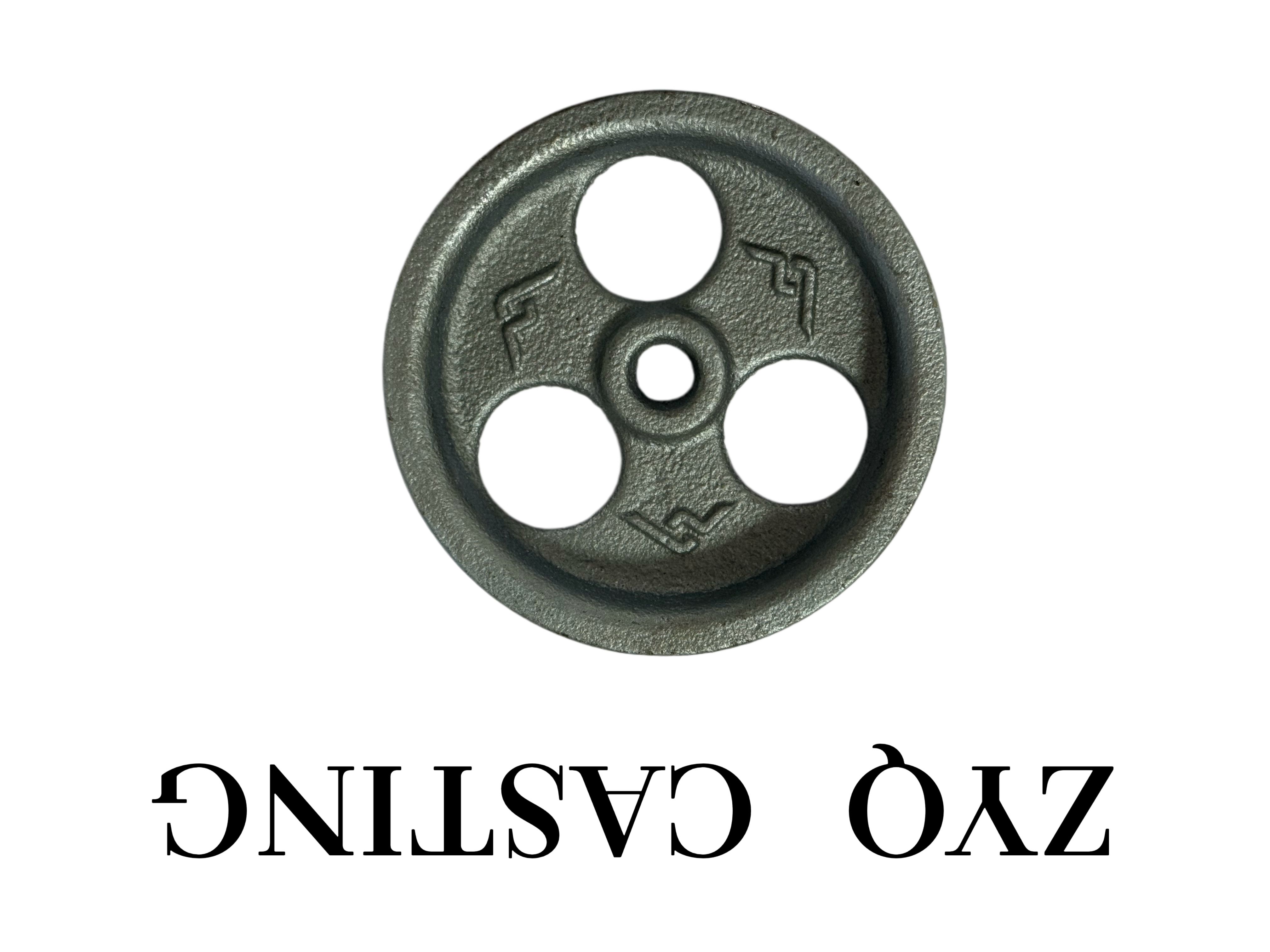
Shell mold casting uses a heated metal pattern and a resin-coated sand mixture to form a thin, rigid mold. The result is a process that sits between ordinary sand casting and investment casting: it delivers better surface finish and dimensional consistency than green sand, but doesn't reach the precision or smoothness of lost wax. Tooling costs are moderate, which makes it attractive for medium production runs of ferrous and non-ferrous parts where die casting's high tooling expense would be hard to justify.
Compared with die casting, the biggest difference is material flexibility and pressure. Die casting relies on reusable steel dies and high injection pressures, so it excels at high volumes of aluminum, zinc, and magnesium, but it struggles with high-melting-point alloys and can trap gas porosity. Shell mold casting is slower and more labor-intensive per part, but it handles iron, steel, and copper alloys without the same porosity risks, and the tooling is typically cheaper for quantities under a few thousand pieces.
When placed next to investment casting, shell mold casting gives up some accuracy and surface quality. Investment casting produces near-net shapes with tight tolerances and excellent as-cast finishes, but the wax patterns, ceramic shells, and longer processing time drive up cost. Shell mold casting is a practical middle ground: it tolerates complex geometries with reasonable detail, costs less than investment casting for many mid-volume jobs, and avoids the extreme lead times and high pattern costs that sometimes accompany lost wax work. Choosing among the three comes down to required tolerance, alloy type, annual volume, and what the budget can absorb.
Choosing the Right Alloy When Every Micron Counts
When tolerances collapse to a few microns, the alloy’s machinability stops being a footnote and starts dictating toolpath strategy. Free-cutting grades with lead or selenium may push chips away cleanly, but they also introduce micro-voids that show up as pits on a lapped surface. A harder, more homogeneous alloy might wear inserts faster yet hold a bore diameter within half a micron across a batch—simply because cutting forces stay consistent from part to part.
Thermal drift is the hidden killer. Two alloys can have identical room-temperature hardness, yet one grows by three microns per 100 mm during a light finishing pass because its thermal conductivity traps heat at the shear zone. For small, thin-walled components, that expansion isn’t theoretical—it becomes a rejected part. Choosing an alloy with moderate conductivity and a low coefficient of thermal expansion isn’t about data sheets; it’s about what the machine can actually hold at the spindle, not on a metrology lab bench.
Grain structure matters more than grade number when every micron counts. Coarse grains can tear away from edges, leaving micro-burrs that no deburring tool can reliably remove without changing the dimension. Ultra-fine grain alloys cut cleaner but sometimes lack the ductility to survive a forming operation upstream. The right choice often sits in between: a stabilized microstructure that has been cold-worked or stress-relieved just enough to keep the second cut from behaving differently than the first.
Design Details That Make or Break Shell Mold Cast Parts
Getting shell mold cast parts right starts well before any metal is poured. One of the first things to scrutinize is wall thickness. Aim for as close to uniform as practical; sudden transitions between thick and thin sections are a common cause of shrinkage porosity and cracking. A minimum wall around 2 mm is feasible on many geometries, but don't treat that as an absolute limit if the flow length is short. Draft angles also demand attention. For shell molding, a draft of 1° to 3° on vertical faces usually pulls cleanly, though deeper pockets or taller ribs may need a bit more to prevent drag marks or mold damage during pattern withdrawal.
Sharp corners are another detail that separates a robust casting from one that fails in service. Internal corners should carry a radius rather than a dead-sharp intersection; this reduces stress concentration and helps the shell fill without eroding the mold surface. External edges can have a smaller radius but still benefit from a slight break. Undercuts are best avoided unless the process is planned around a collapsible core or a secondary operation. A simple, split-friendly parting line keeps costs down and reduces flash, so designers should think about how the pattern will separate from the shell before locking in features.
Finally, watch how ribs, bosses, and lettering are oriented relative to the parting line. Raised features that sit perpendicular to mold withdrawal can cause the shell to grip and tear. Shallow, draft-friendly ribs with generous spacing tend to fill more predictably than tall, crowded ones. Paying attention to these seemingly minor geometry decisions often has a larger impact on scrap rate and finish quality than changing alloy or pouring temperature.
How to Decode an OEM Shell Mold Casting Quote and Avoid Budget Surprises
OEM shell mold casting quotes often hide more than they reveal. The first thing to look at is not the total price, but how the quote breaks down tooling, material, and per-part costs. A low per-unit figure might look attractive, but if the tooling charge is amortized over a short run or listed as a separate, non-recurring expense, your actual budget can balloon. Ask for a line-item breakdown and compare it against your production volume. This simple step exposes quotes that front-load profit into tooling while undercutting the piece price.
Next, pay attention to the alloy specification and tolerance callouts. Shell mold casting can hold tighter tolerances than sand casting, but that precision isn’t free. If a quote lists a generic material grade without a specific ASTM or ISO standard, you might be paying for a premium alloy while receiving a lower-cost substitute. Request the exact material certificate and confirm whether the quoted tolerance matches your part’s critical dimensions. Suppliers who avoid these details often plan to make up margin through secondary machining or scrap recovery—costs you won’t see until later.
Finally, build a buffer for things the quote won’t say. Surface finish requirements, heat treatment, and inspection reports are frequently treated as add-ons. Instead of assuming they’re included, list every post-casting process your part needs and ask the supplier to confirm each one in writing. A quote that seems too simple is often missing post-processing steps. By turning the quote into a checklist rather than a single number, you’ll catch hidden costs before they become purchase-order line items.
In-Process Inspections That Catch Dimensional Drift Before It Reaches You
When a CNC lathe starts drifting by a few microns mid-run, the first sign is rarely a scrap part—it's a subtle shift in tool wear or thermal expansion that most end-of-batch checks miss. In-process inspection closes that gap by measuring critical dimensions while the part is still fixtured, letting the machine or operator react before the deviation becomes a defect. Instead of waiting for a CMM report that arrives too late, you get a running picture of how the process is actually behaving under real cutting conditions.
These checks don't need to be elaborate. Touch probes, laser micrometers, or simple hard gauges integrated into the cycle can track bore diameters, shoulder lengths, or runout at defined intervals. The key is setting control limits that reflect actual process capability—not the full tolerance band—so a trend toward the edge triggers an alert while there's still room to adjust tool offsets, coolant temperature, or fixturing pressure.
What makes this approach stick is the feedback loop. Data from in-process measurements flows directly to the controller or the operator's tablet, showing drift as a live trend rather than a pass/fail stamp at the end. That shift from detection to prediction is what keeps dimensional drift from ever reaching your inspection dock—or worse, your customer's assembly line.
FAQ
Shell mold casting uses a resin-coated sand that forms a thin, hard shell around a heated metal pattern. In an OEM context, the process is tailored to a client's specific part geometry and production volume. Compared with conventional sand casting, the shell mold produces a smoother surface finish and tighter dimensional control because the mold is more rigid and less permeable to metal penetration. It suits medium to high complexity parts where repeatability matters.
Typically linear tolerances around ±0.005 in/in (or ±0.13 mm per 25 mm) are achievable, and some foundries hold even closer limits on select features. Surface finishes often land in the 125–250 RMS range. Actual values shift with part size, alloy, and pattern design. The hard shell reduces mold wall movement, so dimensions stay more consistent than green sand across a production run.
Components with complex external contours, thin ribbing, or require moderate internal cores—like pump housings, valve bodies, gear blanks, and bracket assemblies. It's also a solid fit for parts that need a better as-cast surface than sand casting but don't justify investment casting tooling costs. High-volume runs of smaller ferrous or non-ferrous parts benefit most.
It works with a broad range: carbon steels, stainless steels, alloy steels, ductile iron, gray iron, and some copper-based alloys. Aluminum is less common because the lower pouring temperature doesn't bake the shell as effectively, but it can be done with adjustments. The resin binder system needs to match the metal's pouring temperature to avoid premature shell breakdown or gas defects.
Keep section thickness transitions gradual—avoid abrupt steps that cause hot spots and shrinkage. Draft angles of 1–3 degrees help pattern removal from the shell. Place parting lines to minimize flash on critical surfaces. Cores should have adequate venting and support to prevent shifting. If a feature can be machined later, leaving a small allowance often beats trying to cast an ultra-thin wall or tight hole directly.
They typically use a mix of digital pattern inspection, in-process shell thickness checks, chemical analysis of each heat, and dimensional layout on first articles. Some also run X-ray or dye penetrant testing for critical castings. Because the shell mold is produced from a reusable pattern, consistency from one cavity to the next is strong—assuming pattern maintenance and resin sand mixing stay controlled.
Pattern tooling is the largest upfront expense, though it's simpler and cheaper than die casting or investment casting tooling. Material cost, scrap rate, and post-casting machining drive the per-part price. Larger production volumes spread tooling costs thin, making shell mold casting attractive starting around a few hundred to several thousand pieces per year, depending on part size.
Investment casting generally delivers tighter tolerances and superior surface finish, but at higher tooling and unit costs, especially for medium-sized components. Shell mold casting sits between sand and investment casting: better dimensional accuracy and finish than sand, less than investment, but with lower cost and faster mold production. It's a practical middle ground when the part doesn't need near-net shape on every surface.
Conclusion
A thin resin-sand shell is what lets shell mold casting hold remarkably tight tolerances without the cost spiral of other precision methods. Because the shell is cured against a heated metal pattern, it picks up fine detail and then stays rigid during pouring, so dimensional drift stays small. When you stack that against die casting or investment casting, the differences come down to surface finish, tooling expense, and alloy range—not marketing claims. Shell mold casting tends to win on medium-volume iron and steel parts where a smooth finish and consistent wall thickness matter more than ultra-fine lettering.
Choosing the right alloy is less about chasing exotic grades and more about matching solidification behavior to section thickness. Design details such as uniform walls, generous radii, and correctly placed gates often matter more than the alloy itself. Before you accept a quote, break down tooling, pattern life, and per-piece costs separately; many budget surprises hide in setup charges or pattern rework. And once production starts, in-process checks like shell thickness measurement and early pour sampling catch dimensional drift before it reaches your receiving dock. That combination of design discipline, transparent quoting, and shop-floor inspection is what separates a reliable OEM shell mold casting partner from a one-off supplier.
Contact Us
Contact Person: Nico Yin
Email: [email protected]
Tel/WhatsApp: 8618561567088
Website: https://www.ductileironparts.com/