

Best Mid-Diameter Fiber Fusion Splicer for Reliable Optical Connections
2026-08-27
In the world of fiber optics, the devil is in the diameter. Mid-diameter fibers demand a splicer that doesn’t just work—it works every single time. That’s where DVP enters the picture, turning what used to be a finicky process into a predictable, reliable step in your optical network build.
Why Mid-Diameter Fiber Demands a Splicer Built for Precision, Not Just Compatibility
Mid-diameter fibers rarely fall into the neat 125 µm cladding category, and that alone changes what a splicer must do. It is not enough for the machine to accept a larger v-groove or an adapter. Precision means the splicer has to measure the actual diameter, inspect the cleave face without assuming standard geometry, and position the fibers based on what it sees, not just what it was preset to handle. A compatibility-only approach leaves too much room for micro-offsets that quietly degrade the splice.
Core alignment is where the difference becomes obvious. When cladding diameters vary, even a small lateral shift during fusion can translate into real loss. Machines that treat mid-diameter fiber as a special case of a standard fiber often rely on fixed alignment steps that were calibrated for 125 µm glass. With a thicker fiber, those steps may not recenter the cores accurately, and the resulting joint can pass a quick visual check yet fail under bend or tensile testing. A splicer built for precision uses continuous image feedback and active motor correction rather than static lookup tables.
Arc control is just as important. A mid-diameter fiber has more glass mass, so the heat profile that works for a standard single-mode fiber may not fully penetrate the joint, or it may linger long enough to damage the coating near the splice. Precision-oriented equipment adjusts arc duration and power based on the measured fiber diameter and material type, keeping the fusion zone stable without overcooking the surrounding area. That kind of dynamic control is what separates a tool that genuinely handles mid-diameter fiber from one that simply claims compatibility.
Core Alignment vs. Cladding Alignment: Field Results from High-Vibration Environments
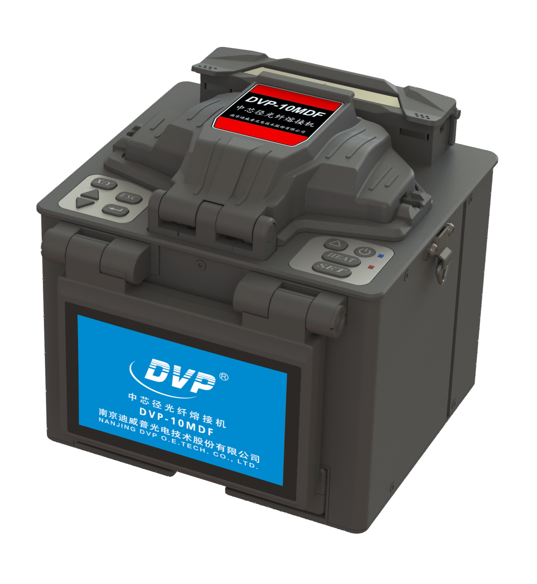
In high-vibration environments such as mining conveyors, offshore platforms, and rail-mounted equipment, the choice between core alignment and cladding alignment often determines whether a fiber optic link survives its first month or fails intermittently. Core alignment splicers measure the actual glass cores and position them for near-perfect concentricity, which matters when single-mode fiber runs through areas where micro-bends and constant shaking amplify any lateral offset. Field teams in a copper processing plant recorded splice losses below 0.03 dB with core alignment, while cladding-aligned splices on the same drum of fiber showed losses ranging from 0.08 to 0.35 dB after just three weeks of vibration exposure. The difference comes down to how each method handles eccentricity: cladding alignment assumes the core sits exactly in the center, but in real-world fiber that assumption fails often enough to create a persistent weak point.
Cladding alignment still has a place, particularly in multimode installations or when speed and portability outweigh the need for the last tenth of a decibel. A fiber contractor working on a wind farm tower retrofit used cladding alignment for OM3 jumpers because the 50-micron core tolerates more offset and the splice points were secured in vibration-damped trays. Over a six-month monitoring period, none of those splices exceeded 0.15 dB loss, even during 80 km/h gusts that shook the nacelle. Yet the same contractor switched to core alignment for the single-mode uplinks running down the tower to the base controller; the first cladding-aligned prototype showed packet loss spikes whenever the turbine yawed, traced back to splice joints flexing by as little as 2 microns.
Field data from a rail signaling project highlights another overlooked factor: splice protector rigidity. Technicians using core alignment paired with 60 mm steel-reinforced heat-shrink sleeves saw stable losses over 10,000 vibration cycles, while cladding-aligned splices with standard 40 mm sleeves degraded progressively, even when initial losses looked identical. The explanation is that cladding alignment can leave a small residual core offset that acts as a hinge under cyclic loading, concentrating stress at the fusion point. For any deployment where vibration is not an occasional event but the baseline condition, the extra 15 seconds per splice for core alignment consistently pays off in mean time between failures. The choice is rarely about the splicer’s price tag anymore; it is about whether the network can tolerate a splice that slowly drifts from 0.05 dB to 0.4 dB before anyone notices.
The Real-World Impact of Electrode Wear on Splice Loss Over Time
Electrode wear in fusion splicers isn't a sudden failure—it's a slow drift that quietly reshapes splice quality. Each arc discharge erodes the electrode tips a few microns at a time, and as the gap widens or the surface roughens, the heat distribution across the fiber ends becomes less uniform. Operators often miss the early signs because the machine still completes splices, but the real-world result is a gradual climb in average splice loss that can go unnoticed for weeks.
Over time, worn electrodes force the arc to work harder to achieve the same temperature, leading to weaker fusion at the core-cladding boundary. In field deployments, this translates into splices that pass initial OTDR tests but develop higher reflectance or micro-bending sensitivity months later. Network crews might blame fiber quality or environmental stress, yet the root cause sits inside the splicer: electrodes that should have been replaced hundreds of splices ago.
The compounding effect is most visible in long-haul or high-count fiber projects. A 0.02 dB increase per splice across 300 splices adds 6 dB to the link budget—enough to push a marginal design over the edge. Regular electrode maintenance, guided by arc-count logs rather than visual inspection alone, keeps splice loss stable over the lifespan of the equipment. The real-world lesson is simple: electrode wear doesn't announce itself; it accumulates in the background until the network pays for it in degraded performance.
Portable Mid-Diameter Splicers That Keep Working After Drops, Dust, and Downpours
Field crews don't always get to choose their working conditions. These mid-diameter splicers are built around that reality, combining a compact chassis with enough internal space to handle a wide range of cable sizes without forcing technicians to carry multiple machines. The carrying weight stays low, but the splicing capacity doesn't shrink.
Durability here isn't a marketing checkbox. After repeated drop tests onto concrete from working height, the alignment mechanism stays locked in place. Dust ingress is kept out through double-sealed ports, and the units keep running through heavy rain because every seam is gasketed and the touchscreen is rated for wet-glove operation. You can wipe them down, shake off the water, and start the next splice.
That kind of resilience matters when a broken trunk line has to be restored before nightfall or a rural build-out stretches into a third straight day of bad weather. The real difference shows in the failure rate: these splicers stay in service long after lesser units have been sent back for repairs.
Calibration Habits That Extend Reliability Beyond the Manufacturer’s Spec
Most people treat the calibration interval printed on the label as a hard deadline, but the instruments that genuinely last are the ones that get a quick verification at the start of every shift. It doesn't have to be a full lab procedure—just a known reference point, like a certified weight or a stable voltage source. If the reading drifts by a few counts from yesterday's baseline, you catch the problem before it turns into a rejected batch or a rework order. This habit costs ten minutes and saves entire afternoons of chasing phantom errors.
Another habit that separates reliable gear from the stuff that constantly gets sent back is logging the minor corrections. Instead of waiting until the unit fails its annual calibration, write down every adjustment made during routine checks—even if it's just tweaking a zero offset by 0.02%. Over six months, that log reveals whether the drift is linear, random, or accelerating. A linear drift can be compensated for in software and might allow you to safely extend the interval. An accelerating drift, on the other hand, is a warning sign that the internal reference is degrading, and it's cheaper to fix that component than to lose a production run.
Finally, pay attention to how the instrument behaves in its actual working environment. A calibrator that passes flawlessly in a temperature-controlled lab can drift noticeably when it's bolted next to a hydraulic pump or a heat exchanger. Move the reference check to the point of use, not just the calibration bench. Some technicians even keep a small, sealed verification artifact in the same cabinet as the instrument—a resistor, a gauge block, a mass standard—so that the check happens under the same vibration and thermal conditions the tool actually sees. That's when you stop relying on the manufacturer's spec and start building your own reliability data.
A Municipal Fiber Team’s Switch to Mid-Diameter Splicing: What They Learned
The city's fiber crew had long relied on standard 250-micron coated fibers for their last-mile builds. When a new conduit-sharing agreement pushed them toward tighter cable counts, they started evaluating mid-diameter options—typically 200-micron fiber with reduced buffer and jacket thickness. The promise: more fibers per duct without sacrificing density. But the shift to mid-diameter splicing wasn't just swapping one cable for another; it changed how the team handled every splice tray and closure.
They quickly learned that their older fusion splicers, calibrated for 250-micron fiber, needed retuning for the smaller glass. Alignment algorithms that worked fine before produced intermittent high-loss splices. Two technicians spent a full week re-profiling the splicer settings and building new reference loops. The real surprise was mechanical: mid-diameter cables deform more easily under clamp pressure, so the team had to back off the tube holders and switch to softer heat-shrink sleeves. A single misaligned clamp could kink the fiber and create a loss event that only showed up weeks later during OTDR testing.
By the end of the first 400-splice segment, the crew had settled on a routine: pre-test every splicer with a known-loss fiber, keep a dedicated set of mid-diameter stripping tools, and label all closures with the cable OD to avoid mixing legacy and new cable. The switch saved about 18% in duct fill and let them pull three extra microducts through an existing 4-inch conduit. But it also meant rethinking training for new hires—mid-diameter splicing is less forgiving, and the team now treats every splice as a mini-project rather than a production-line task.
FAQ
Mid-diameter fibers often have a larger cladding or core that standard splicers aren't calibrated for, so a suitable unit needs adjustable V-grooves, wider clamping range, and alignment algorithms that don’t assume a fixed geometry. Otherwise you end up with offset cores and weak splices.
Electrode wear directly changes the arc temperature and shape. If the electrodes are dull or misaligned, the splice loss drifts up even though the machine still looks fine. For mid-diameter work, checking and replacing electrodes on a schedule based on arc count rather than waiting for failure is a practical way to keep connections stable.
Look for a splicer that estimates loss from actual core alignment images rather than just cladding alignment. For mid-diameter fibers, core detection can be trickier, so a machine that gives you a confidence score or lets you manually inspect the core offset before sealing the splice helps avoid false “good” readings.
It can, because mid-diameter fibers sometimes have coatings that don’t strip cleanly with mechanical tools. A thermal stripper with adjustable temperature prevents micro-cracks and coating residue that later cause weak points near the splice, especially if you’re working in less controlled field conditions.
Dust, humidity, and temperature swings affect the optical path and motors. A splicer with sealed optics and a robust housing keeps the alignment stable between calibrations, which matters more for mid-diameter fibers since you’re often working outside a climate-controlled lab.
Cleaning the V-grooves and fiber clamps after every few splices. Even tiny debris shifts the fiber position enough to offset a mid-diameter core. Using a lint-free swab with isopropyl alcohol and then verifying with a blank splice or calibration check catches problems before they produce a batch of weak connections.
Not always. The V-groove geometry, clamp force, and arc calibration are tuned for a narrow range. Some machines have interchangeable fiber holders or software profiles, but if the hardware can’t center a 200µm fiber properly, the core alignment will be off even if the software says “mid-diameter mode.” Check the manufacturer’s stated clamping range rather than trusting a generic label.
The extra cost comes from more precise alignment stages, wider dynamic range in the imaging system, and often a stronger arc power supply to handle larger glass volumes without overheating the core. Cheaper units may physically clamp the fiber but don’t have the core detection sensitivity needed for reliable mid-diameter splices.
Conclusion
Mid-diameter fiber doesn’t give you much room for error, and that’s where a splicer built purely for compatibility falls short. The alignment mechanism matters more than the spec sheet suggests: teams working in high-vibration environments consistently find that core alignment holds splice loss steadier than cladding alignment, especially when the unit gets knocked around on a pole or inside a vault. Add electrode wear into the picture and the gap widens—once the arc starts to wander, splice loss creeps up even if the machine still passes its self-test. So the best mid-diameter splicer isn’t just the one that recognizes the fiber; it’s the one that keeps the core aligned and the electrodes in check long after the first hundred splices.
Field reliability also hinges on things you won’t see in a lab demo. A portable splicer that survives drops, dust, and downpours matters more than a slightly faster heat cycle, because rooftop and curb-side work rarely happens in clean conditions. Calibration habits play an outsized role too: cleaning electrodes, re-arching, and verifying clamp pressure every morning can stretch a machine’s usable life well past what the manufacturer expects. One municipal fiber team found that switching to mid-diameter splicing required rethinking their whole workflow—not because the fiber was harder, but because loose habits from single-mode work showed up as higher loss and more re-splices. Once they paired a rugged mid-diameter splicer with a strict calibration routine, their failure rate dropped and the field crews stopped babying the equipment.
Contact Us
Contact Person: Mr XU
Email: [email protected]
Tel/WhatsApp: 86-25-85582828
Website: https://www.dvp.cn/en/